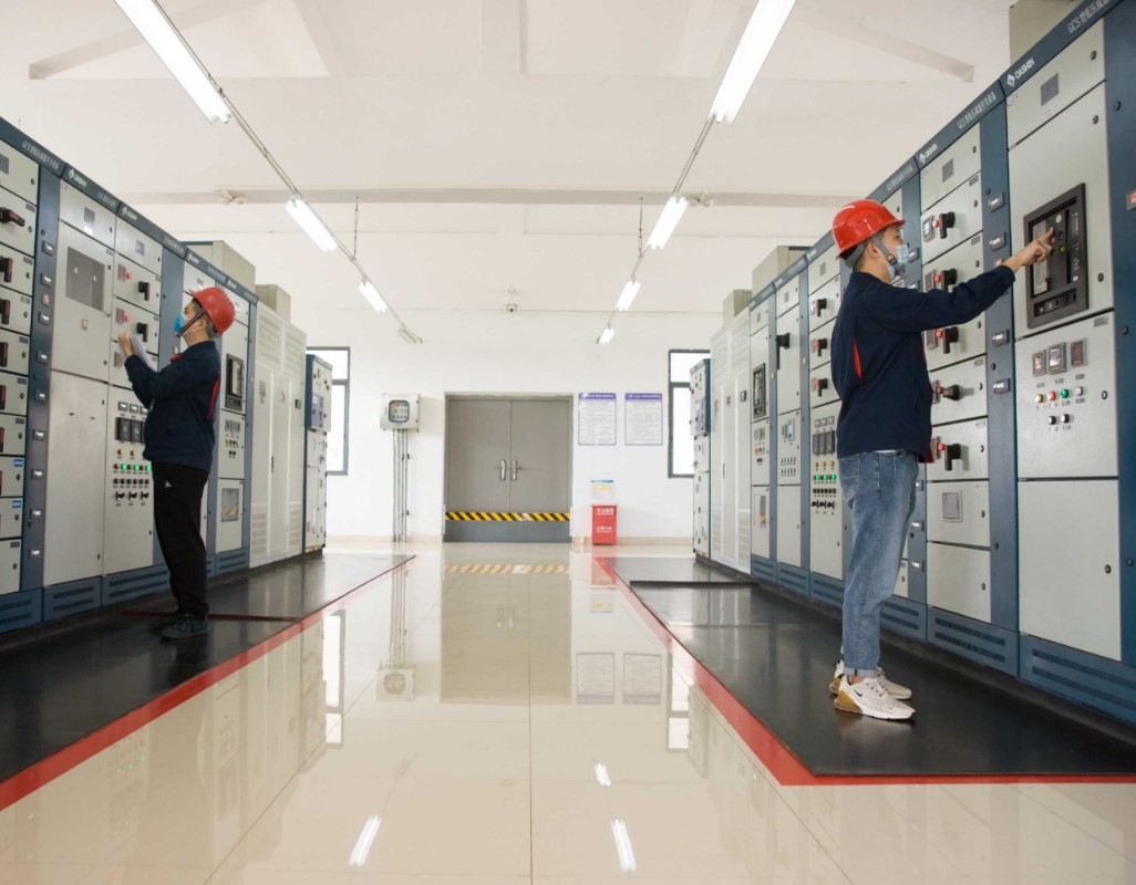

Low-Voltage Switchgear: How Low-Voltage Components Build a Complete Power Distribution System
Electrical Manufacturer: How Low-Voltage Switchgear Is Built from Electrical Components
As a professional electrical manufacturer, understanding how individual low-voltage electrical components are integrated into a complete power distribution system is essential.
A Low-Voltage Switchgear cabinet is not a single electrical product. It is an engineered electrical assembly consisting of a Distribution Box or Switchgear Enclosure, busbars, wiring systems and different low-voltage components such as MCBs, MCCBs, AC Contactors, Relays and Terminal Blocks.
For an electrical manufacturer, the quality of the final switchgear depends not only on the performance of individual components, but also on correct system design, component coordination, assembly, wiring and testing.
What Is Low-Voltage Switchgear?
Low-Voltage Switchgear is an electrical assembly designed to receive, distribute, control and protect electrical power in low-voltage systems.
It is widely used in:
-
Industrial factories
-
Commercial buildings
-
Infrastructure projects
-
Machinery and equipment
-
Utility distribution systems
-
Solar and renewable energy systems
-
Water treatment facilities
-
HVAC systems
-
Data centers
A professional electrical manufacturer normally selects and integrates different electrical components according to the voltage, current, short-circuit capacity, number of outgoing circuits and operating requirements of each project.
In simple terms:
Distribution Box + Low-Voltage Components + Busbars + Wiring = Low-Voltage Switchgear
How Does an Electrical Manufacturer Build Low-Voltage Switchgear?
The production of low-voltage switchgear involves several stages.
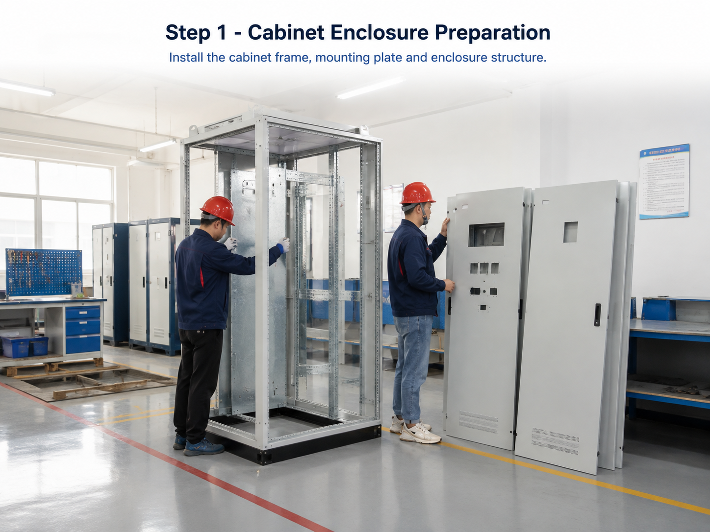
Step 1 – Switchgear Enclosure Preparation
The first stage is preparation of the Distribution Box or Switchgear Enclosure.
The enclosure provides the mechanical structure required to install and protect all internal electrical components.
Depending on the project, an electrical manufacturer must consider:
-
Cabinet dimensions
-
Indoor or outdoor installation
-
IP protection level
-
Mounting method
-
Cable entry
-
Internal compartment arrangement
-
Ventilation
-
Maintenance space
The cabinet frame, doors, mounting plates and internal supports are assembled before the electrical components are installed.
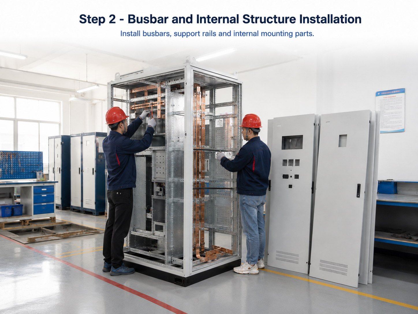
Step 2 – Busbar and Internal Structure Installation
After the cabinet structure has been prepared, the next stage is installation of the internal support system and busbars.
The busbar system distributes electrical power from the incoming circuit to the outgoing circuits.
A typical three-phase low-voltage switchgear may include:
-
L1 busbar
-
L2 busbar
-
L3 busbar
-
Neutral busbar
-
PE / Earth bar
Copper or aluminum busbars may be selected according to the design requirements.
An experienced electrical manufacturer must consider rated current, short-circuit withstand capacity, temperature rise, insulation distance and mechanical strength when designing the busbar system.
Step 3 – Installation of Low-Voltage Electrical Components
After the mechanical structure and busbars are completed, different low-voltage electrical products are installed inside the switchgear.
This is where individual electrical components become part of a complete power distribution system.
Typical components include:
Miniature Circuit Breaker – MCB
The MCB is commonly used for branch circuit protection.
Its primary functions include:
-
Overload protection
-
Short-circuit protection
-
Circuit isolation
MCBs are commonly used for lighting circuits, socket circuits, small equipment and auxiliary circuits.
Molded Case Circuit Breaker – MCCB
The MCCB is generally used for higher-current incoming and outgoing circuits.
Typical applications include:
-
Main incoming protection
-
Feeder protection
-
Industrial load protection
-
Motor circuits
-
Generator circuits
A common electrical distribution configuration is:
Incoming Power → Main MCCB → Busbar → Outgoing MCCB / MCB → Load
The electrical manufacturer must correctly coordinate upstream and downstream protection devices according to the system requirements.
AC Contactor
An AC Contactor is used when electrical loads need frequent switching or automatic control.
Typical applications include:
-
Motors
-
Pumps
-
Fans
-
Compressors
-
HVAC equipment
-
Lighting
-
Industrial machinery
A typical motor control circuit may be:
MCCB / MCB → AC Contactor → Protection Relay → Motor
The contactor performs switching, while the circuit breaker and protection devices provide electrical protection.
Relays
Relays are widely used for control, signaling, interlocking and protection.
Inside low-voltage switchgear, relays may work together with:
-
Contactors
-
Circuit breakers
-
Push buttons
-
Indicator lights
-
Timers
-
PLC systems
-
Protection devices
For an electrical manufacturer, proper relay selection helps create more reliable and flexible control circuits.
Terminal Blocks
Terminal Blocks provide organized connection points for power and control wiring.
They are commonly used for:
-
Incoming cables
-
Outgoing cables
-
Control wiring
-
PLC connections
-
Sensor connections
-
Neutral conductors
-
Protective earth connections
Professional terminal block arrangement helps improve wiring efficiency, maintenance and troubleshooting.
Step 4 – Wiring and Electrical Connection
After all electrical components have been installed, the devices must be connected according to the electrical schematic.
The wiring process may include:
-
Main power cables
-
Control wiring
-
Auxiliary circuits
-
Signal wiring
-
Neutral wiring
-
PE / grounding conductors